
 Technical Information Power And Control Cables Power Appendixes Fire Performance of Cable Fire Performance of Cable(standards of tests )
 صفحه Fire Performance of Cable(standards of tests )
|
DURATION OF SYSTEM CIRCUIT INTEGRITY IN THE BUILDING LAWS : The duration of the system circuit integrity depends on how long the supply of electrical services must continue in the event of a fire. National legislations in most countries provide requirements for safety systems which have to be met. DEGREE OF ACIDITY OF COMBUSTION GASES : Corrosive gases act with moisture to produce aggressive acids which corrode metal parts and cause extensive long-term damage, even though the fire damage may only be limited; this is because corrosive gases often spread throughout a building through the ventilation system or withing whole installations. The damage may not be limited to the area immediately affect ted by the fire. Electronic units and electronic contacts are particularly vulnerable, as are free-standing or concrete enclosed steel constructions. The most popular plastic containing halogens is PVC (polyvinyl- chloride). In case of fire or at high temperature PVC starts to degradate. Hydrochloric acid and other fission products are generated and leads to extremely aggressive corrosion. Therefore the current trend is to replace the halogen containing plastics with halogen free ones. For instance PVC is currently being replaced at a large scale with polyolefin i.e. polyethylene. SMOKE DENSITY : The formation of smoke has several unpleasant consequences. On one hand it considerably lowers the visibility in a fire event, thus impeding the people trapped inside closed rooms escape of and the efforts of the firemen to carry on their rescue and fire fighting actions. On the other hand it produces smoke poisoning because of the carbon monoxide. Regarding the formation of the combustion gases the PVC comes off quite badly. |
|
|
Evacuation : In many countries a duration of 30 minutes is considered sufficient for alarm and evacuation of people. Compliance with this requirement with regard to the systems (fire alarm systems, emergency lighting, passenger hoists, smoke exhaust, voice alarm and acoustic signalling, escape route signalling) . For special buildings like high-rise buildings, hospitals, tunnels, prisons, a duration of 60 to 90 minutes can also adequate. |
 |
|
Fire fighting : Besides rescuing time for people extra time for the work of the fire brigades must be allocated. Mostly 90 minutes afterthe fire starts are regarded sufficient for fire fighting. The uninterrupted power supply of the electrical systems used for this (e.g. sprinkler water pumps, mechanical smoke exhausts, firemen lifts) |
|
|
Planning : Planning an electrical safety system means finding answers o the questions: Which parts of the building requires which level of safety? Which electrical system has to be supplied for how long? Which circuits are involved (safety circuits)? Which is the best cable routing for these circuits? Are there restrictions concerning fire load, etc.? |
|
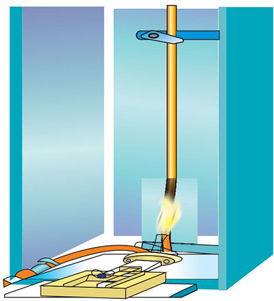 |
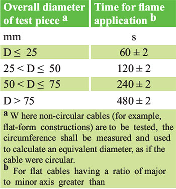
EC 60332-1 This standard is applied for general FLAME RETARANDCY test,on single vertical insulate wire or cable. FLAME RETARDANT Flame retardant cables are cables which, when installed as a single cable, although ignitable on exposure to flame source, will greatly reduce flame spread and self-extinguish once the flame source is removed. However in a vertical cable bundle, e.g. in vertical risers, fire can spread along the cables (chimney effect). In order to avoid this danger, the so called «non-flame propagating» cables should be used. Time of flame application is given in table 1 IEC 60332-1. |
|
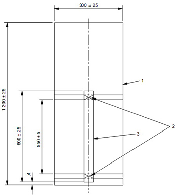
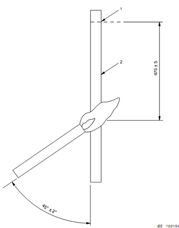
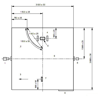
Standard Summary: A sample of cable is fixed on a vertical support with length of 550+/-5 mm. A gas burner is ignited and applied on the cable at the angle of 45o and 475 mm far from upper grip. A lead wire or a cable is being aflamed with a propane-air- burner (1 kW flame). The burning cable should self-extinguish as soon as the fire source has been removed. The fire damage may not be higher than 60 cm. The test is considered to be passed if: The sample has not burned and the damage (carbonisation) has not reached any of the terminations of the sample (> 50 mm). standards IEC 60332-1, EN 60332-1 |
 |
 |
 |
 |
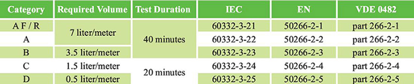
IEC 60332-3 The series of International Standards covered by Parts 3-10, 3-21, 3-22, 3-23, 3-24 and 3-25 of IEC 60332 specifes methods of test for the assessment of vertical fame spread of vertically- mounted bunched wires or cables, electrical or optical, under defned conditions. It cannot be assumed that, because a wire or cable meets the requirements of IEC 60332 parts 1 and 2, a vertical bunch of similar cables or wires will behave in a similar manner. This is because fame spread along a vertical bunch of cables depends on a number of features, such asvolume of combustible material exposed to the fre , the geometrical confguration of the cables ,, the quantity of combustible gas released from the cables for a given temperature rise ,the construction of the cable , ..... . |
|
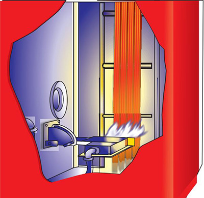
Test procedures This test simulates the chimney effect in vertical cable installations. In a standardized cabinet the cable bundle is kept in a burner fre for 20 - 40 minutes (gas burner 75 ± 5 MJ/h). Thereby the temperature is kept constant to 750 °C. Depending on the volume of the non-metal (combustible) materials per running meter it can be differentiated in the categories A F/R, A, B, C and D . The cables must self-extinguish after removing the fre source. The fre may not have propagated any further than 2.5 m from the burner. |
|
 |
|
 |
 |
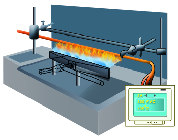 |
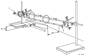
IEC 60331 IEC 60331-11 specifes the test apparatus to be used for testing cables required to maintain circuit integrity when subject to fre alone where the test condition is based upon a fame with a controlled heat output corresponding to a temperature of at least 750 °C. IEC 60331-21 specifes the test procedure and gives the performance requirement, including a recommended fame application time, for cables of rated voltage up to and including 0.6/1.0 kV required to maintain circuit integrity when subjected to fre under specifed conditions |
|
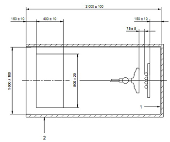
Standard Summary: The cable sample, as described in the relevant procedure in part 21 onwards of IEC 60331, shall be held horizontally by means of suitable supports at each end of the sheathed or protected portion. The source of heat shall be a ribbon type propane gas burner with a nominal burner face length of 500 mm with Venturi mixer. The burner face shall be positioned in the test chamber so that it is at least 200 mm above the foor of the chamber and at least 300 mm from any chamber wall. The fame application time shall be as specifed in the relevant cable standard. In the absence of such a cable specifcation, a 90 min fame application is recommended With reference to the test procedure ; the cable possesses the characteristics for providing circuit integrity so long as during the course of the test : - the voltage is maintained i.e. no fuse fails or circuit-breaker is interrupted; - a conductor does not rupture, i.e. the lamp is not extinguished. Test standards : IEC 60331-11 and -21, DIN VDE 0472-814 |
|
 |
|
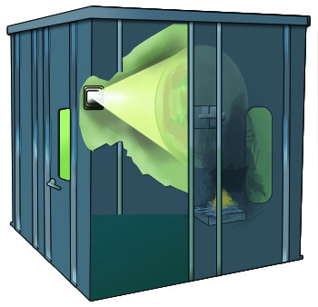 |
IEC 61034 The measurement of smoke density is an important aspect in the evaluation of the burning performance of cables as it is related to the evacuation of persons and accessibility for fre fghting. IEC 61034 is published in two parts, which together specify a method of test for measurement of smoke density of cables burning under defned conditions . IEC 61034-2 provides details of the test procedure to be employed for the measurement of the density of smoke emitted from cables burning under defned conditions. It describes the means of preparing and assembling cables for test, the method of burning the cables, and gives recommended requirements for evaluating test results |
|
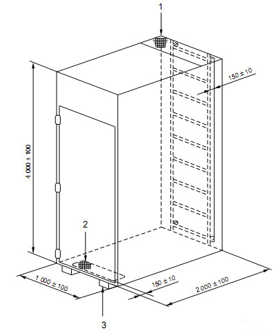
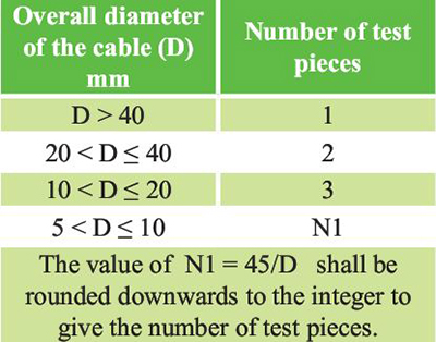
Test procedures A length of 1 meter cable and the number of samples acc to table 5.2.1 of IEC 61034-2 are prepared and burnt in cubic room with 27m3volume. Light transmittance is measured for I0and Itin 40 minutes of test duration. The density of smoke emission can be determined by measuring of the light penetrability. Cable samples are lit with alcohol in a test chamber (cubical with an edge length of 3 m). The so formed smoke is uniformly spread by a ventilator and influences the light measuring section. The test is considered to be passed when the following light penetrability is reached to specifed value. The performance requirements for a particular type or class of insulated conductor or cable should preferably be given in the individual cable standard. In the absence of any given requirement, it is recommended that a value of 60 % cable light transmittance is adopted as a minimum for any cable tested against this standard. Test standards IEC 61034, EN 61034 |
 |
 |
 |
 |
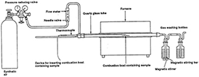
IEC 60754 IEC 60754-1 specifes a method for the determination of the amount of halogen acid gas, other than hydrofuoric acid, evolved during the combustion of compounds based on halogenated polymers and compounds containing halogenated additives taken from cable constructions. IEC 60754-2 specifes a method for the determination of the degree of acidity of gases evolved during the combustion of compounds taken from cable components. A pre-determined quantity of the test material is burned in a tube furnace. The evolved gases are trapped by bubbling through bottles flled with distilled or demineralized water. The acidity is measured by determination of pH value. The conductivity of the solution is also measured. |
|
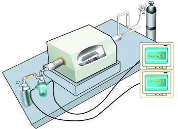
What is Halogen ? The halogens are the elements of the 7th group in the Periodic Table of Elements: chlorine (Cl), fuorine (F), bromine (Br), iodine (I). Halogen free cables must be free of chlorine, fuorine and bromine (PVC cables contain halogen, PVC = Polyvinyl chloride). The halogens are an integrated component of many acids : HCl = Salt acid (hydrochloric acid) ; HF = Hydrogenfuorid ; HBr = Hydrogenbromid . Test procedures : 1000 mg insulation material is burned in a combustion furnace at 935 °C with pre-defned air supply for over 30 minutes. By means of two gas washing containers, held in the airfow the conductivity and the pH-value are measured. Like that even small quantities of halogen containing substances can be detected and proven. The test is considered to be passed when the ph-value > 4.3 and the conductivity < 10 µS/mm . Test standards IEC 60754-2, EN 50267-2-2 |
|
 |
|